Wednesday, August 3, 2022

Lesson 08: Start Camera and Roll

 In this post understand cameras space and Perspective and Orthographic  projections interactively.


The cube can be rotated using x, y and z keys. The The camera space can be changed by checking LookAt checkbox and supplying  varying input for Position, Target and Up vectors. 
Similarly, Perspective Projection can be changed by checking Perspective checkbox and supplying  varying input for FOV, Near  Plane and Far Plane.  The FOV can be changed by typing page up and down keys or mouse wheel.
Orthographic Projection can be changed by checking Orthographic checkbox and supplying  varying input for X minmax, y minmax and Z minmax values. 

Monday, July 25, 2022

Understanding View space, Perspective and Orthographic Projections

So far our camera was in a fixed position and transformations happened in object space.  In this post we will  look at the larger picture.

As shown in the diagram below, a 3D object in a scene starts off from object space. Model transformation places it in the world space.  Based on the camera position the entire world is transformed into Camera space or view space. This is called view transform. This is done using viewing matrix. It is later moved to screen space using Projection matrix.


So far in our examples, camera is located at the origin and view and projection matrixes are not computed; instead identity matrix is used.  Next we will try to move around the camera and understand different type of projections.

Model Matrix
Model Matrix is responsible for moving 3D objects  from object space to world space. The affine transformation discussed in Lesson 06 are applied.

View Matrix
When the hypothetical camera position is changed, the whole world is transformed around it using view matrix. The view matrix is computed as below from glm as below.
mat4 lookAt(vec3 const& eye, vec3 const& center, vec3 const& up);
The internals is as described below (courtesy : learnopengl.com).
 

1. Camera position
The camera position or eye is a vector in world space that points to the camera's position. 

2. Camera direction vector
The  Camera direction vector is the direction at which the camera is pointing at. This is computed from the scene's origin or center in this case it's  (0,0,0). Subtracting the camera position vector from the scene's origin vector thus results in the direction vector. This must always point to +Z axis by RHS convention.

3. World up vector
The up vector (0,1,0) points to worlds Y axis. This may not be always the case.

4. Right axis vector
The right axis vector represents the positive x-axis of the camera space. This is obtained by doing a cross product on the up vector and the camera direction vector from step 2. 

5. Up axis vector
The Up axis vector points to camera's positive y-axis. It's computed by the cross product of the right and direction vector.

Output:

As mentioned earlier,  the World up vector need not be always (0,1,0).
For example,  if  the camera is moved on top of the cube say (0, 3, 0), we will be looking at the  top of the cube.  The eye is (0,3,0), center is (0,0.0) and up is (1, 0, 0) not (0,1,0).

Projections
The final matrix is projection matrix. There are two types of projections
Orthographic and Perspective. The traits are as below.


The following shows another view with the view frustum. A view frustum is a rectangular box that confines the image rendered to be shown on the screen. 


The volume or the frustum is defined by the left, right, top, bottom, near and far plane values. 

The perspective projection is computed in glm as below
perspective(float fovy, float aspect, float zNear, float zFar);
In Perspective projection, the frustum appears as a truncated pyramid. 
fovy is the  Field of View (FOV) or zoom factor 
aspect is the aspect ratio of the viewport. i.e., width/height.
ZNear is the distance from the camera to the near plane
ZFar is the distance from the camera to the far plane
Example:
perspective(45.0, 1.84, 1.0, 100.0)
The screenshot below shows the perspective projection of the colored cube rotated 20 degree pitch and 20 degree yaw.

The ortho projection is computed in glm as below
ortho(xmin, xmax, ymin, ymax, zmin, zmax);
xmin, xmax are left and right of the view frustum
ymin, ymax are top and bottom of the view frustum
ZMin is the distance from the camera to the near plane
ZMax is the distance from the camera to the far plane
In orthogonal view it appears as a cube. 
Example: ortho(-1.84, 1.84, -1.0, 1.0, 1.0, 100.0); The 1.84 is the aspect ratio.
The screenshot below shows the orthographic  projection of the colored cube rotated 20 degree pitch and 20 degree yaw.

Unproject
Sometimes it's useful to x,y,z coordinates in the object space based on the mouse cursor position. UnProject() accomplishes this.  
The X,Y coordinates from the mouse cursor position and Z value from the depth buffer is used to compute the window coordinates. Later this is passed to glm unProject() along with Model, View and Projection Matrix, to get the co ordinates in world space.
For example, 

In the above, the red dot in the cube represents mouse cursor position  x = 353 y = 168
from depth buffer Z = 0.79
Using  Model, View, and Perspective Projection matrices, the world space coordinate is calculated as
0.22, 0.12, 0.43.


Tuesday, July 19, 2022

Lesson 07:Drawing Text interactively.


As discussed in the  previous article, Text can be drawn in multiple fonts, sizes and colors. Also can be moved around. It's implemented in Lessons\Lesson07 project.


Monday, July 18, 2022

Drawing Text


Modern OpenGL does not support drawing text so it needs to be handled independently. There many popular libraries available such as freetype.
Instead, using GDI Plus APIs text can be drawn into a memory based bitmap. Later the bitmap is loaded as a texture.

Implementation
A new mesh class - TextMesh is defined for loading bitmap as texture. It's used by DrawTextUtil object for loading vertex data and texture data to the vertex and fragment shaders.
DrawTextUtil  uses GDIPlus to create ARGB in memory bitmap containing text to be drawn. The size of the bitmap should be multiples of 128. i.e.,  128, 256, 512 etc.
First bitmap is filled with black color and then Text is drawn using the font and color. Note the text color needs to be non black. Font can be changed by passing LOGFONT structure, Also text color can be changed by passing COLLOREF of the color.
Fragment shader is modified to discard non text fragments for blending with the background.

Client
Client needs to first Startup() GDIPlus in the beginning of the application and Shutdown()  at the end.
Instantiate DrawTextUtil   object by Init() method supply unique texture id and size.
UpdateFontandColor() should be called to supply font details and text color.
DrawText() can be called to draw text. 
The DrawTextUtil   object can be translated, rotated etc.  just like any 3D object.


Sunday, July 17, 2022

Lesson06:Understanding Affine Transformation interactively.


 In this post we shall understand affine transformations interactively the three kinds of affine transformations: Scale, Translate and Rotation on X, Y and  Z axes as discussed in the previous post.

The GUI has two windows - Console Window with OpenGL context. This renders a Cube with a texture having each of the 6 faces labeled as below.


Launch Lessons\Lesson06.exe.  Use the input dialog to change values. The cube also be rotated using X,Y, Z keys and using Mouse inputs.

Input Dialog
Provides an user interface to experiment interactively - scaling, translation and rotation.  First input is provided in the input text boxes. It's submitted for rendering the cube when Apply button is clicked. The cumulative value is updated in the caption. Reset button resets values. Both + and -ve values can be submitted. Note:- The values are applied when the associated checkboxes are checked.


Camera 
As we are still passing Identity matrix for view and projection matrices, the camera is sitting at the origin (0,0,0) looking down on -Z axis. In this scenario, the back face is visible with x=0, y=0, z=-0.5.

Scale
First rotate cube by 30 degree pitch and 30 degree yaw. Enter different values for scaling in x, y and z axes.

Translate
First rotate cube by 30 degree pitch and 30 degree yaw. Enter different values for translation in x, y and z axes.

Rotate
As noted earlier, the rotation happens in counter clockwise direction along the axis. The diagram below maps faces to numbers.
Rotation around X axis
Rotate the cube by 90 degrees increments. The sequences of faces that should display are as below.


Rotation around Y axis
Rotate the cube by 90 degrees increments. The sequences of faces that should display are as below.

Rotation around Z axis
Rotate the cube by 90 degrees increments. The sequences of faces that should display are as below.
Order of Transformation
Following order is used:
  1. Scale
  2. Rotate by Z,X,Y
  3. Translate
Note in code, the matrix would be computed in reverse order as below.
       
		M = mat4(1);
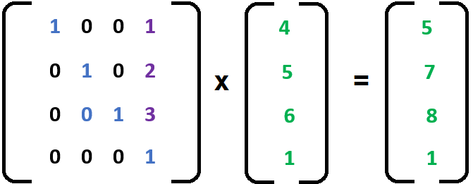
		M = translate(M, translateby);
		M = rotate(M, radians((float)(yaw)), vec3(0.0f, 1.0f, 0.0f));
		M = rotate(M, radians((float)(pitch)), vec3(1.0f, 0.0f, 0.0f));
		M = rotate(M, radians((float)(roll)), vec3(0.0f, 0.0f, 1.0f));
		M = scale(M, scaleby);


Saturday, July 16, 2022

Essential 3D math - Matrices

OpenGL uses matrix operations for a lot of purposes. For example, translations, scaling, rotations. Also computing of projection matrices, view matrices etc.
OpenGL uses 4x4 matrix used in homogenous coordinate system. Where each coordinate is represented as [x,y,z,w].Where w=1 for the affine transformations such as  translations, scaling, rotations. W can be any floating point number in the range -1.0 to 1.0 for projection matrices. During rasterization x, y, z coordinates are computed as  x/w, y/w and z/w. This is known as perspective divide.

OpenGL uses columnar matrix multiplication as shown below.

Identity Matrix
A special matrix having all elements along diagonal as 1 as shown below. 
It is associative, I*M = M*I = M. It's used in the computation of rotation, translation and scaling as discussed below.


Translation Matrix
Translation matrix is used for moving around 3d objects.
Example:
Let's say there is a point [1,2,3] and want to translate by [4,5,6]. It can be accomplished as below. Resulting in  [5,7,9].

Scaling Matrix
Scaling matrix is used for Shrinking or Expanding 3d objects.


Example:
Let's say there is a point [1,2, 3] and want to  scale by [2,2,2]. It can be accomplished as below. Resulting in  [2,4,6].

Rotation
In 3D, rotation happens independently  on three cardinal axes X, Y, and Z.
Pitch or Rotation on X axis
The following matrix represents rotation matrix on X axis.

Example:
Let's say there is a point [1,2, 3] and want to  rotate by 90 degrees in X axis. It can be accomplished as below. Resulting in  [1,-3,2].
Yaw or Rotation on Y axis
The following matrix represents rotation matrix on Y axis.
Example:
Let's say there is a point [1,2, 3] and want to  rotate by 90 degrees in Y axis. It can be accomplished as below. Resulting in  [3,2,-1].


Roll or Rotation on Z  axis
The following matrix represents rotation matrix on Z axis.

Example:
Let's say there is a point [1,2, 3] and want to  rotate by 90 degrees in Z axis. It can be accomplished as below. Resulting in  [-2,1,3].


Friday, July 15, 2022

Essential 3D math - Vector

Following math concepts are essential for further understanding.

A 3D vector is represented as [Vx, Vy,  Vz] where  Vx, Vy and Vz represent numbers in 3D cartesian space. Vectors are attributed with a direction represented by its head  and a magnitude computed as square root of the squared sums of its components.


Unary negation and scalar multiplication 
The  negation and multiplication is done on all the components.
For example consider a vector
v=[1,2,3] so  2*v results in [2,4,6]. Similarly -v results in [-1,-2,-3].

Addition and Subtraction
Vectors can be added or subtracted. Here the individual components are added or subtracted. 
For example consider two vectors  A[1,2,3] and B[4,5,6]. 
A+B = [(1+4), (2+5), (3+6)] = [5, 7, 9].
A-B =  [(1-4), (2-5), (3-6)] = [-3, 3, -3].
Graphically represented as below, Note that the direction has changed  when arguments are reversed.

Unary Vectors
also known as normalized vectors are represented as V^  have magnitude of 1. 

For Example V = [3,2,1]. It's normalized vector is calculated as
[2,3,1]/sqrt(4+9+1) = [3/3.74, 2/3.74, 1/3.74]=[0.8, 0.53, 0,27]


Dot Product
Dot Product of  two vectors is equal to the product of their magnitudes and the cosine of the angle between them. The notation used is a.b where a and b are vectors. It's mathematically represented as
a ·b = |a| x |b| x cos(θ).
It's graphically represented as 


To compute angle between two unit vectors, mathematically it can be represented as

The dot product may be a positive  or a negative or a zero.


Cross Product
Cross Product of  two vectors is equal to the product of their magnitudes and the sine of the angle between them. The notation used is axb where a and b are vectors.
Mathematically it's represented as

Cross product yields a vector that is perpendicular to the plane of two vectors a and b. Graphically it's represented as


The cross product of two vector is equal to area of their parallelogram.


Lesson05: Multi-Colored Cube


In this post we will try to draw a multi colored cube as shown above. The cube looks elongated because aspect ratio is not applied.

Implementation

MultiColorCube class is implemented as below to draw the single colored cube. 
 It's located in VOGLLib\Geometry\Cube\MultiColorCube.h.
       
//Implements multi colored cube 
class MultiColoredCube :public BaseGeometry
{
public:
	//OpenGL initialization
	void Init()
	{
		//initialize opengl context
		BaseGeometry::Init(new CubeMesh());
		//generate vbo data
		kount = mesh->GenerateVerticesData(false, VAOUtil::POS | VAOUtil::CLR, vaoutl);
		//setup vertices
		vaoutl.SetupVBO(0, VAOUtil::POS);
		vaoutl.SetupVBO(1, VAOUtil::CLR);
		vaoutl.unbindVAO();
	}

	//override
	virtual string vertexShaderSource()
	{
		return R"(
		#version 330 core
		layout (location = 0) in vec3 vVertex;
		layout (location = 1) in vec3 vColor;
		out vec3 fcolor;

		uniform mat4 transform;

		void main()
		{
		   gl_Position =  transform * vec4(vVertex, 1.0);
		   fcolor = vColor;
		};
		)";
	}

	//override
	virtual string fragmentShaderSource()
	{
		return R"(
		#version 330 core
		in vec3 fcolor;
		out vec4 FragColor;
		void main()
		{
		   FragColor = vec4(fcolor,1.0);
		};
		)";
	}
};
 
Lesson05 Project

This purpose of this Lesson05 project is to create a Window initialized with OpenGL context and draw a MultiColorCube with 6 colors one for each face.
As discussed in introduction create tutorial lesson project Lesson02 under Lessons folder.
Add a header file Scene.h as shown below. The class itself is self explanatory. 
The WM_CLOSE  event is  handled in OnCloseWindow function and the window is destroyed and  application is shutdown. 
The Init method calls BaseScene's Init to create hosting window and OpenGL Context. It also attaches BaseCameraInputHandler to rotate the cube either by keyboard or mouse inputs.
The DrawScene method draws the cube with multiple colors and rotates as per keyboard or mouse inputs.
The Cleanup method release the resources.
The Scene class is implemented as below. It's located in Lessons\Lesson05\Scene.h file.
       
#include "Scene\BaseScene.h"
#include "Geometry\Cube\MultiColoredCube.h"

class Scene:public BaseScene
{
public:
	//message handler
	BEGIN_MSG_MAP(Scene0)
		MESSAGE_HANDLER(WM_CLOSE, OnCloseWindow)
		CHAIN_MSG_MAP(BaseScene)
	END_MSG_MAP()

	//override
	int Init(RECT rect, WCHAR *windowname)
	{
		//create host window and context
		BaseScene::Init(rect, windowname);
		//attach mouse keyboard input handler
		mskbd = new BaseCameraInputHandler(m_hWnd);

		//Create multicolor cube
		cube.Init();
		
		return 0;
	}

	//release resources
	void Cleanup()
	{
		cube.Cleanup();
		delete mskbd;
		
	}
	
	//draw the scene
	void DrawScene()
	{
		glClear(GL_COLOR_BUFFER_BIT | GL_DEPTH_BUFFER_BIT);
		//get model view projection matrix. 
		//only model is modified
		//view and projection will be identity matrix
		mskbd->fetchCameraData(&cube.camera);
		cube.Draw();

	}

	//Close the window
	LRESULT OnCloseWindow(UINT uMsg, WPARAM wParam, LPARAM lParam, BOOL& bHandled)
	{
		bHandled = TRUE;
		DestroyWindow();
		PostQuitMessage(0);
		return 0;
	}


private:
	MultiColoredCube cube;
}; 
 
The main.cpp is located in Lessons\Lesson05\main.cpp file. It creates the scene object and calls its init method.
       
#include "Scene.h"

Scene scene;

int WINAPI WinMain(HINSTANCE inst, HINSTANCE prev, LPSTR cmd_line, int show)
{
	scene.Init(RECT{ 100, 100, 780, 500 }, L"Modern OpenGL-Tutorial - Lesson05");
	scene.ShowWindow(show);

	MSG msg;
	while (GetMessage(&msg, 0, 0, 0)) 
	{
		TranslateMessage(&msg);
		DispatchMessageA(&msg);
	}

	return 0;
}     
 
The output looks as shown in the top. The cube is rotated by 20 degrees pitch and 20 degrees yaw. The camera position at the origin looking down on -Z axis or the back face of the cube.
To rotate the cube X,Y and Z keys can be used. They rotate respectively pitch, yaw and roll the cube  by 10 degrees.
In the next post we shall learn essential 3d Math.

Thursday, July 14, 2022

Lesson04:Textured Cube

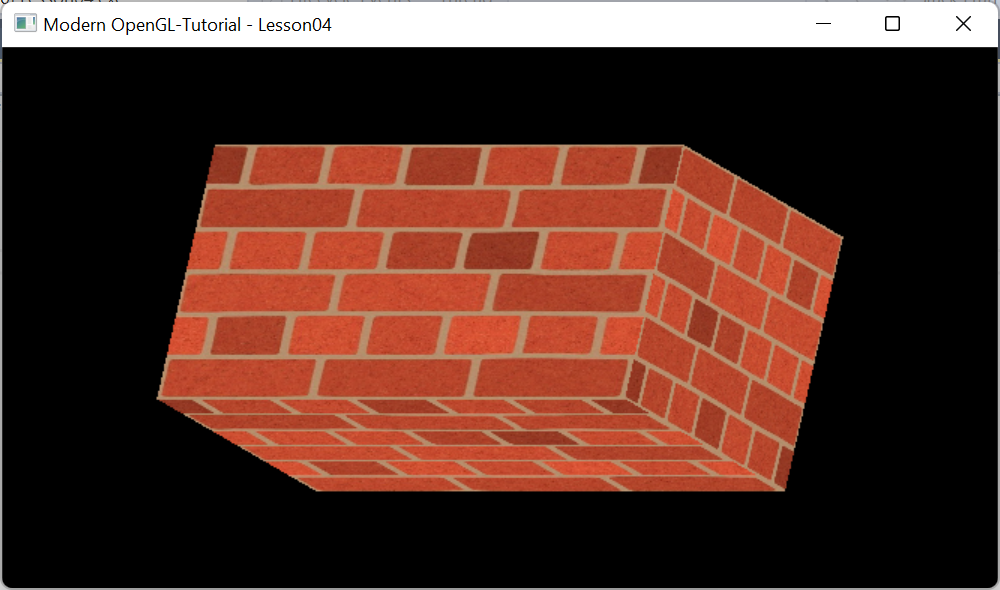
 A Texture is 2D image that can be wrapped around a 3D object like a gift wrapper. For example, resources\textures\bricks2.jpg is a 2D Texture file. 

Unlike cartesian coordinates, Texture follow UV  System as shown below.

TextureUtil Class is used for loading textures. It uses SOIL2 library discussed earlier to implement it.
It's located in VOGLLib\Geometry\TextureUtil.h.

Loading Texture
OpenGL supports up to 80 Textures and each with its own identifier. Loading textures is implemented in LoadTexture method in TextureUtil class.
SOIL_load_OGL_texture(filename.c_str(), SOIL_LOAD_AUTO, 0, SOIL_FLAG_MIPMAPS | SOIL_FLAG_INVERT_Y);
       
MIPMAP
Mipmapping is a technique where a high-resolution texture is downscaled and filtered so that each subsequent mip level is a quarter of the area of the previous level. This means that the texture and all of its generated mips requires no more than 1.5 times the original texture size. An example is shown below.


Inversion of Y Axis
After loading the image needs to be inverted since the V axis of the texture and Y axis of OpenGL  have opposite polarity.

Wrapping
As shown below, determines how the texture is wrapped.

Texture Filtering
Texture filtering is a method that is used to improve the texture quality in a scene. Without texture filtering, artifacts like aliasing generally look worse. Texture filtering makes textures look better and less blocky.

Applying Texture
As discussed previously, Texture coordinates are passed during rendering. The following mapping in relation to the UxV axes is used as texture coordinates for the vertices consecutively.
       
       //first triangle
		{  0.0,   1.0,   0.0 },
		{ -1.0,   0.0,   0.0 },
		{  0.0,  -1.0,   0.0 },
       //second triangle
		{  1.0,   0.0,   0.0 },
		{  0.0,   0.0,  -1.0 },
		{  0.0,   0.0,   1.0 },
        
Implementation

TexturedCube class is implemented as below to draw the textured cube. 
 It's located in VOGLLib\Geometry\Cube\TexturedCube .h.
       
#pragma once
#include "..\BaseGeometry.h"
#include "..\TextureUtil.h"
#include "CubeMesh.h"
//implements texturedcube
class TexturedCube:public BaseGeometry
{
public:
	//initialize
	void Init(GLushort	texunit, const string& filename)
	{
		//create mesh and the window
		BaseGeometry::Init(new CubeMesh());
		//generate VBOs for position and Texture coordinates
		kount = mesh->GenerateVerticesData(false, VAOUtil::POS | VAOUtil::TEX, vaoutl);
		//setup vertices
		vaoutl.SetupVBO(0, VAOUtil::POS);
		vaoutl.SetupVBO(1, VAOUtil::TEX);
		vaoutl.unbindVAO();
		this->filename = filename;

		//Load Texture from the file
		texutl.Init(texunit);
		texutl.LoadTexture(filename);
	}

	//update uniforms
	void UpdateUniforms()
	{
		//pass builtin texture to the fragment shader 
		texutl.MakeActive(shader.GetUniformLocation("tex"));
		BaseGeometry::UpdateUniforms();
	}

	//release resources
	void Cleanup()
	{
		BaseGeometry::Cleanup();
		texutl.Cleanup();
	}

	//override
	virtual string vertexShaderSource()
	{
		return R"(
		#version 330 core
		layout (location = 0) in vec3 vVertex;
		layout (location = 1) in vec2 vTexCrd;
		uniform mat4 transform;
		out vec2 FragTexCrd; 
		void main()
		{
			gl_Position = transform * vec4(vVertex, 1.0);
			FragTexCrd=vTexCrd;
		};
		)";
	}

	//override
	virtual string fragmentShaderSource()
	{
		return R"(
		#version 330 core
		in vec2 FragTexCrd;
		out vec4 FragColor;
		uniform sampler2D tex;
		void main()
		{
		   FragColor = texture(tex, FragTexCrd);
		};
		)";
	}

private:
	TextureUtil  texutl;
	std::string filename;
};   
 

This purpose of this Lesson04 project is to create a Window initialized with OpenGL context and draw a TexturedCube wrapped with texture.
As discussed in introduction create tutorial lesson project Lesson04 under Lessons folder.
Add a header file Scene.h as shown below. The class itself is self explanatory. 
The WM_CLOSE  event is  handled in OnCloseWindow function and the window is destroyed and  application is shutdown. 
The Init method calls BaseScene's Init to create hosting window and OpenGL Context. It also attaches BaseCameraInputHandler to rotate the cube either by keyboard or mouse inputs. It initializes the IndexedCube with texture.
The DrawScene method draws the cube with loaded texture  and rotates as per keyboard or mouse inputs.
The Cleanup method release the resources.
The Scene class is implemented as below. It's located in Lessons\Lesson03\Scene.h file.
       
#include "Scene\BaseScene.h"
#include "Geometry\Cube\TexturedCube.h"

class Scene:public BaseScene
{
public:
	//message handler
	BEGIN_MSG_MAP(Scene0)
		MESSAGE_HANDLER(WM_CLOSE, OnCloseWindow)
		CHAIN_MSG_MAP(BaseScene)
	END_MSG_MAP()

	//override
	int Init(RECT rect, WCHAR *windowname)
	{
		//create host window and context
		BaseScene::Init(rect, windowname);
		//attach mouse keyboard input handler
		mskbd = new BaseCameraInputHandler(m_hWnd);

		//Create cube an set texture filename
		cube.Init(0, R"(..\..\resources\textures\bricks2.jpg)");
		
		return 0;
	}

	//release resources
	void Cleanup()
	{
		cube.Cleanup();
		delete mskbd;
		
	}
	
	//draw the scene
	void DrawScene()
	{
		glClear(GL_COLOR_BUFFER_BIT | GL_DEPTH_BUFFER_BIT);
		//get model view projection matrix. 
		//only model is modified
		//view and projection will be identity matrix
		mskbd->fetchCameraData(&cube.camera);
		cube.Draw();

	}

	//Close the window
	LRESULT OnCloseWindow(UINT uMsg, WPARAM wParam, LPARAM lParam, BOOL& bHandled)
	{
		bHandled = TRUE;
		DestroyWindow();
		PostQuitMessage(0);
		return 0;
	}


private:
	TexturedCube cube;
};   
 
The main.cpp is located in Lessons\Lesson03\main.cpp file. It creates the scene object and calls its init method.
       
#include "Scene.h"

Scene scene;

int WINAPI WinMain(HINSTANCE inst, HINSTANCE prev, LPSTR cmd_line, int show)
{
	scene.Init(RECT{ 100, 100, 780, 500 }, L"Modern OpenGL-Tutorial - Lesson04");
	scene.ShowWindow(show);

	MSG msg;
	while (GetMessage(&msg, 0, 0, 0)) 
	{
		TranslateMessage(&msg);
		DispatchMessageA(&msg);
	}

	return 0;
}
 
The output looks as shown in the top. The cube is rotated by 20 degrees pitch and 20 degrees yaw. The camera position at the origin looking down on -Z axis or the back face of the cube.
To rotate the cube X,Y and Z keys can be used. They rotate respectively pitch, yaw and roll the cube  by 10 degrees,
In the next post we shall create a colored cube with transformation.